1. Notes
Step gauges are precision measuring instruments. Abnormal force must be prevented from bringing to them. For example, to lift the step gauge by grabbing the blocks, to strike the blocks with any objects, to bring abnormal force to blocks, to drop the step gauge from a height, to bend the body of the step gauge with powerful force, etc. must be avoided.
Anyi-Step has two kinds of blocks: ceramic and steel. Attention must be paid to the rust protection of steel blocks and the spacers between blocks. Under harsh environment, attention must also be paid to the rust protection of the body of step gauge.
2. Preparation before use
1). Take out the step gauge from the packing carefully (refer to the above notes), dip the clean absorbent cotton into some aviation gasoline (#120) and clean the working surfaces of step gauge and the surface of the base (no dissolving detergent should be used).
2).When calibrating the positioning accuracy of X-axis or Y-axis, the body of step gauge must parallel the direction of guide rail (the obliquity 100: 0.01). When calibrating the Z-axis, make the end face of step gauge stand vertically on the supporting surface. If the perpendicularity of the supporting surface and Z-axis is not good,
manage to make some correction. When fixing the step gauge, the clamping points must be the supporting parts of the Airy points of the step gauge. Clamping mustn't cause bending and deforming.
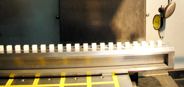
3) Fix a micrometer dial on the suitable place of the equipment to be calibrated. This micrometer dial can be a micron dial test indicator or a horizontal stylus probe. Expected accuracy decides what kind of micrometer dial should be used.The repeatability must be as good as possible. Coordinate measuring machines and height gauges, etc. can use their own probes for the calibration, unnecessary to use micrometer dial . When clamping the micrometer dial with a magnetic stand, the rigidity and stability of the magnetic stand must be good.
a)For machining centers and other similar machine tools, the micrometer dial must be fixed on the spindle head frame.
b)For lathes, the micrometer dial must be fixed on the cutter frame.
c)For others, the fixing place is similar to the above.
4). Constant temperature
After adjusting the place of step gauge and mirometer dial, wait until their temperature and the temperature of the object to be calibrated reach the same level. The time of waiting for constant temperature depends on the temperature range of step gauge and the equipment to be calibrated and the ambient temperature.The higher the calibrating accuracy needs, the longer the time of waiting for constant temperature should be.Under normal circustances, 4 – 8 hours is enough for the time of waiting for constant temperature. If making high precision calibration, the time of waiting for constant temperature. should be 12 – 24 hours or more. If the temperature difference beteen the step gauge and the equipment to be calibratied is not big , then the time of waiting for the constant temperature can be shorter.
5). Warm-up of equipment
Ater the time of waiting for the constant temperature, the equipment to be calibrated should be in sufficient operation before the calibration begins. At this time, the equipment's temperature and accurace, etc. shows its real performance , the step gauge is nearer the state of the object to be calibrated.
3. Calibrating
1). Move the guide rail of the equipment to be calibrated to its origin, then make the stylus probe of the micrometer dial touch the center of the origin working surface and compress the stylus probe, then set the enumerator of the guide rail and the micrometer dial to zero.
2). Move the stylus probe along the direction which is perpendicular to the guide rail and out of the working surface of the gauge blocks.
3). Move the stylus probe along the direction which is parallel to the guide rail and to the next point to be calibrated.
4). Repeat the second procedure reversely, the displacement should be the same (namely move the stylus probe to the center of the current working surface of the gauge block.
5). Fine adjustment of the equipment to be calibrated
Two methods are optional: One is to adjust the equipment to the nominal value that the guide rail displays. Now the differential between the guide rail and the step gauge can be read directly from the micrometer dial. The other is to adjust the equipment to the origin of the micrometer dial, now the differential between the guide rail and the step gauge can be read directly from the enumerator of the guide rail. The first method is the first choice when the repeatability, resolution and accuracy of the micrometer dial are higher than those of the equipment to be calibrated, this method can bring more precision result. One measurement can use only one method. Two methods can't be used one measurement.
Special notice should be taken to the parts to be calibrated: The step gauge has uni-directional and bi-directional working surfaces. The working surfaces which are in the same direction that the guide rail moves are usually used. If the uni-directional and bi-directional working surfaces along a direction are used, the error of reverse of direction of the guide rail and the micrometer dial will be included in the calibration result, unles the error is very small or the error is the calibration target.
4. Data processing
The measured value plus the error of the step gauge's relevant point are the error of the calibrated point of the guide rail. The symbol of plus and minus must be paid attention to when processing the data. For high precision calibration, the coefficient of thermal expansion, the temperature deviation from standard temperature and the error of step gauge, etc. should be considered in data processing. Due to limited space, they are not discussed here.
After data processing, correction to the positioning accuracy of the guide rail can be carried out based on the result.

|
